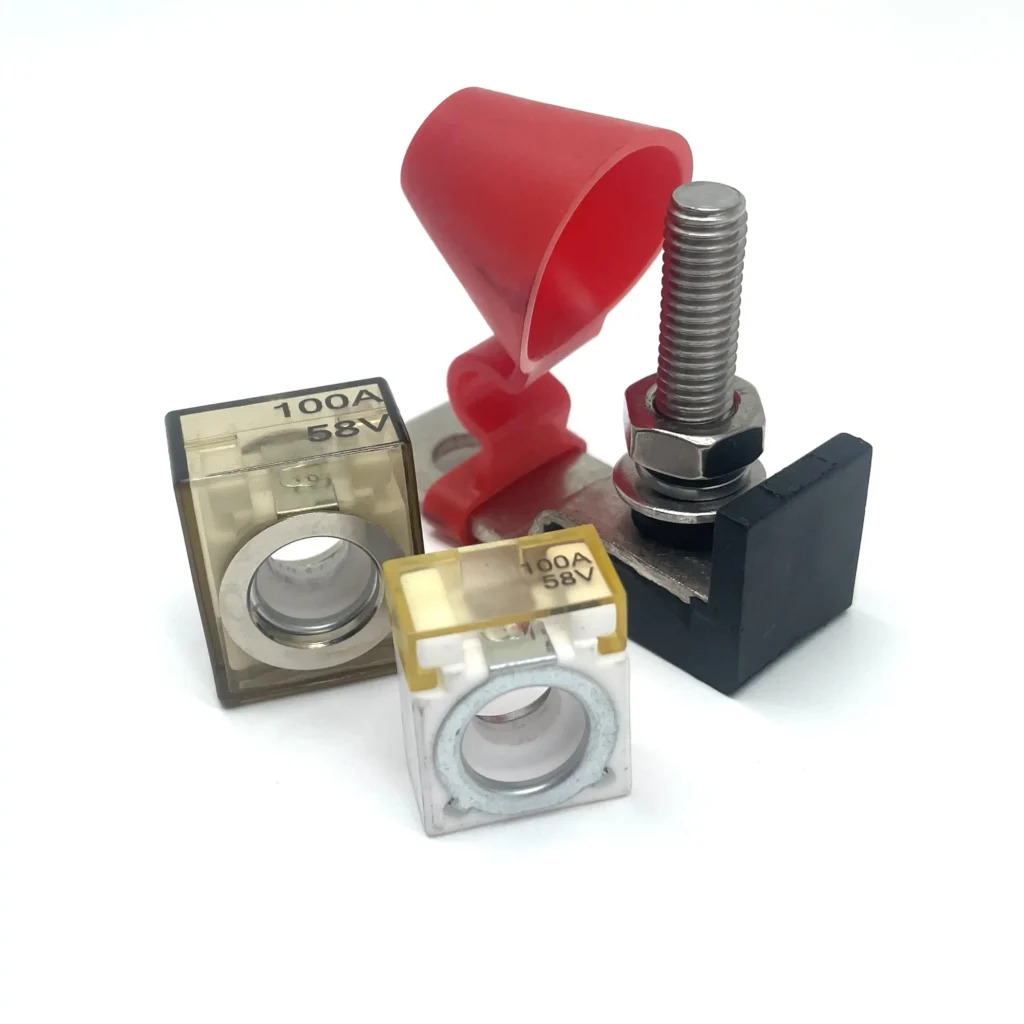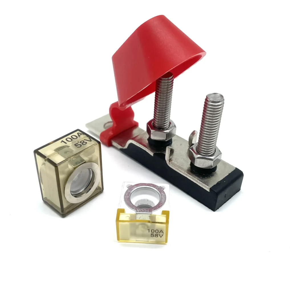
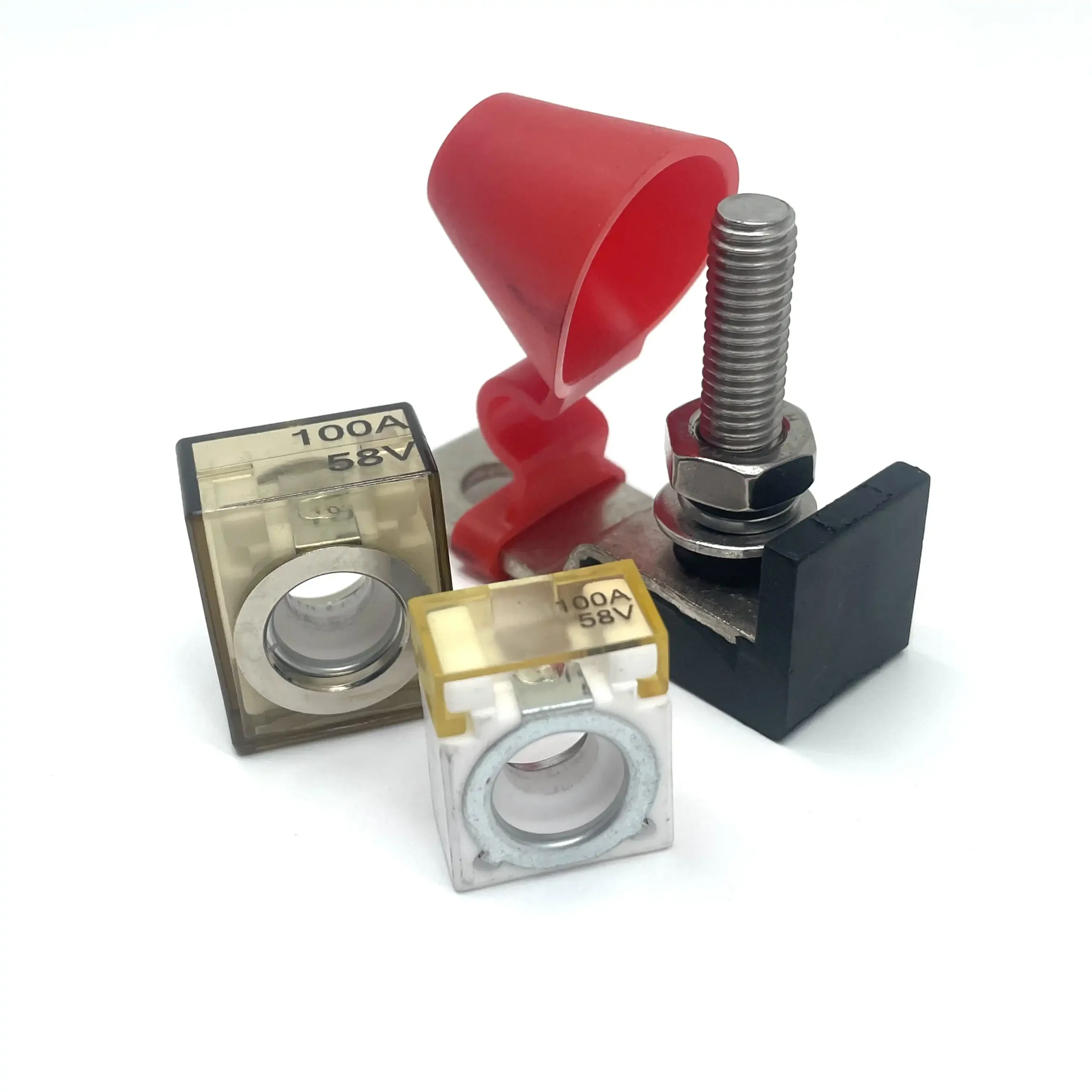
Quick answer: An MRBF fuse holder is a compact high-current DC fuse mounting device designed for Marine Rated Battery Fuses. It is commonly installed close to a battery or power distribution point. Single holders protect one branch circuit, while dual holders provide two separately fused branches. Correct selection depends on system voltage, load current, conductor size, fuse rating, holder limits and installation conditions.
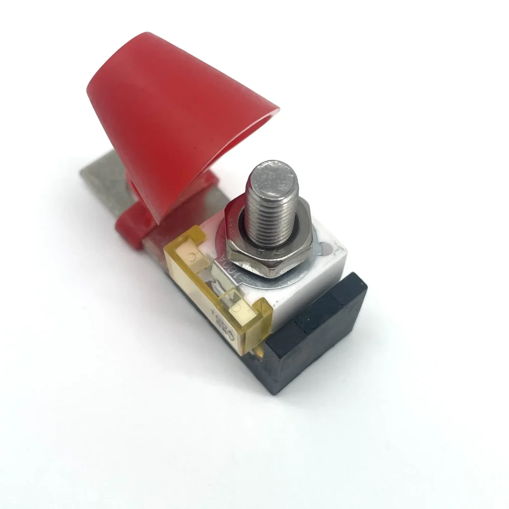
An MRBF fuse holder is a compact mounting and connection device designed for a Marine Rated Battery Fuse (MRBF). It is commonly used in high-current DC systems where circuit protection needs to be installed close to a battery or power distribution point without using a large remote fuse enclosure.
MRBF systems are widely used in automotive, marine, RV, auxiliary battery, inverter and other low-voltage DC applications. Established MRBF fuse families are available in ratings from 30A to 300A, with maximum voltage ratings up to 58V DC. These are fuse-family specifications, however, and should not be assumed to apply automatically to every fuse holder. Fuse rating, holder rating and cable ampacity must be checked separately.
Key Takeaways
- An MRBF fuse is the overcurrent protection device; the holder provides mounting and electrical connection.
- Single MRBF holders provide one protected branch; dual holders provide two separately fused branches.
- A dual holder does not automatically provide twice the total current capability.
- Voltage rating, current capability, cable ampacity and fuse interrupt rating are separate design considerations.
- High-current connections depend heavily on correct terminal fit, clean contact surfaces and proper tightening.
- A protective cover helps reduce accidental contact and exposure, but should not be treated as a specific IP rating without documented testing.
How Does an MRBF Fuse Holder Work?
The holder provides the mechanical support and electrical connection points required to place an MRBF fuse in series with a DC circuit.
In a typical terminal-mount arrangement, the holder is positioned near the battery or power source. The MRBF fuse is secured to the fuse connection, and the outgoing conductor connects to the protected side of the circuit.
When current exceeds the fuse’s time-current characteristic for long enough, the fuse opens the circuit. The holder itself does not perform the fusing action.
The holder performs several other important functions:
- Secures the MRBF fuse mechanically.
- Maintains a low-resistance electrical connection.
- Supports cable lugs and fastening hardware.
- Provides a stable high-current connection point.
- Helps reduce accidental contact around exposed terminals.
This distinction matters because a correctly selected fuse can still be installed in a connection that overheats if the holder, cable lug, conductor, fasteners or contact surfaces are undersized, loose, damaged or contaminated.
Why Are MRBF Fuse Holders Used Near Batteries?
A terminal-style MRBF system provides a compact way to position overcurrent protection close to a source capable of delivering high fault current.
Typical applications include:
- Main DC battery feeds
- Inverter circuits
- Auxiliary battery systems
- Automotive power distribution
- RV and camper electrical systems
- Marine DC systems
- Battery switch connections
- Bus bar and distribution connections
- High-current accessory circuits
In U.S. recreational boat applications subject to applicable federal requirements, overcurrent protection is required on certain battery output conductors and is generally located close to the battery.
Official MRBF terminal fuse-block documentation likewise identifies applications such as DC mains and inverter circuits and emphasizes high-current protection where installation space is limited.
Single vs Dual MRBF Fuse Holder
MRBF fuse holders are available in different circuit configurations. The two most common layouts are single and dual.
| Feature | Single MRBF Fuse Holder | Dual MRBF Fuse Holder |
|---|---|---|
| Fuse positions | 1 | 2 |
| Protected branches | 1 | 2 |
| Typical use | One high-current branch from the source | Two separately fused branches from one source |
| Selection focus | Voltage, current, fuse, cable and connection quality | Same checks plus total holder current limit |
| Current assumption | Check the holder specification | Do not assume each branch can carry the holder’s full maximum current |


Single MRBF Fuse Holder
A single MRBF fuse holder provides one fuse position for one protected circuit.
It is appropriate when one battery terminal or high-current source needs to feed one protected branch, such as:
- Battery to inverter
- Battery to a main distribution point
- One auxiliary high-current circuit

Dual MRBF Fuse Holder
A dual MRBF fuse holder provides two fuse positions, allowing two circuits to be protected separately from the same source connection.
This can be useful when one battery needs to feed, for example:
- A power distribution system and an inverter
- Two independent auxiliary systems
- Two separate high-current branches
The key point is that a dual holder does not automatically double the current capability.
Some dual terminal fuse blocks specify one maximum current for the complete holder. One established dual design explicitly states that the total current of the entire fuse holder must not exceed 300A, rather than allowing two independent 300A circuits.
The fuse rating of each branch and the holder’s total current limit therefore need to be checked separately.
What Voltage Rating Should You Consider?
MRBF systems are mainly used in low-voltage DC electrical systems. Established MRBF fuse series are available with maximum voltage ratings up to 58V DC, but that does not mean every MRBF holder on the market is automatically suitable for 58V DC.
Check these three values independently:
- Fuse maximum voltage
- Fuse holder maximum voltage
- Maximum voltage the electrical system can actually reach
The third point matters because nominal system voltage and actual operating voltage are not always the same. A charging system can operate above the nominal battery voltage.
or road-vehicle single-bolt fuse-links, ISO 8820-6:2019 covers devices with rated voltages up to 58V and rated currents up to 300A.
The fuse and holder should therefore be suitable for the maximum circuit voltage they may experience.
What Current Rating Should You Choose?
A common mistake is selecting the fuse from the largest ampere value that physically fits the holder.
For example, a holder that can accept a high-current fuse does not mean the circuit should automatically use the maximum available fuse rating.
Fuse selection should consider:
- Normal operating current
- Expected peak current
- Cable ampacity
- Cable length
- Allowable voltage drop
- Insulation temperature rating
- Ambient temperature and installation conditions
- Equipment requirements
- Available fault current
A more reliable design sequence is:
1. Determine the Load
Identify the normal operating current and expected peak current of the connected equipment.
2. Select the Conductor
Choose the conductor based on current, circuit length, allowable voltage drop, insulation temperature and installation conditions.
3. Select the Fuse
Choose a fuse that permits normal operation while providing appropriate protection for the conductor and downstream circuit.
4. Check the Holder
Confirm that the fuse holder is suitable for the selected fuse, system voltage and expected current.
5. Check Interrupt Rating
Battery systems can produce substantial fault current. The fuse’s interrupt rating therefore matters in addition to its ampere rating.
Published MRBF fuse data show that interrupt capability can change with system voltage, so the ampere value printed on the fuse is not the only electrical specification that should be checked.
How Do You Choose the Right MRBF Fuse Holder?
1. Circuit Configuration
Choose a single holder when one protected branch is required. Choose a dual holder when two separately fused branches need to originate from the same source.
2. Maximum Voltage
The holder must be suitable for the highest voltage the circuit can experience.
3. Current Capability
Check the holder’s maximum current capability.
For dual models, confirm whether the specified maximum applies to each circuit or to the complete holder.
4. Fuse Compatibility
Confirm the MRBF fuse dimensions, current range and mounting arrangement required by the holder.
Do not assume that every physically similar battery fuse is interchangeable.
5. Stud and Terminal Size
MRBF terminal fuse holders commonly use M8 fuse studs, although mounting arrangements and cable-lug requirements can vary between designs.
The fuse, lug and hardware need to be mechanically compatible.
6. Conductive Materials and Contact Quality
High-current connections depend on low contact resistance.
Important details include:
- Conductive material
- Plating
- Surface condition
- Cable-lug fit
- Fastener quality
- Tightening torque
- Assembly quality
A high-current holder should not be evaluated only by the appearance of its plastic body.
7. Protective Cover and Environment
An insulating or protective cover can help reduce accidental shorts and exposure around the terminals.
For wet, dusty, marine or engine-compartment applications, verify the environmental rating of the specific product rather than assuming every covered holder provides the same level of protection.
8. Installation Space
Check the full installed assembly, not only the bare holder.
Space is required for:
- Fuse
- Cable lug
- Washer and locking hardware
- Nut
- Protective cover
- Cable bend radius
- Access for installation and servicing
What Should You Check Before Installation?
Before installing an MRBF fuse holder:
- Disconnect the power source before beginning work.
- Confirm the system voltage.
- Confirm normal and maximum expected load current.
- Verify cable size and cable-lug size.
- Check that the fuse and holder ratings are compatible.
- Inspect studs, nuts, washers and contact surfaces.
- Make sure cable lugs and fuse contact surfaces are clean and undamaged.
- Follow the hardware order specified for the product.
- Follow the torque specification for the specific holder.
- Make sure the cable connection does not electrically bypass the fuse.
- Confirm that the protective cover can close correctly.
- Provide sufficient clearance around the battery, terminals and connected cables.
After installation, inspect the circuit during initial operation for signs such as:
- Abnormal temperature rise
- Discoloration
- Loose hardware
- Unusual voltage drop
- Softened or damaged insulation
Persistent abnormal heating should be investigated rather than treated as normal.
Cozy MRBF Fuse Holder Options
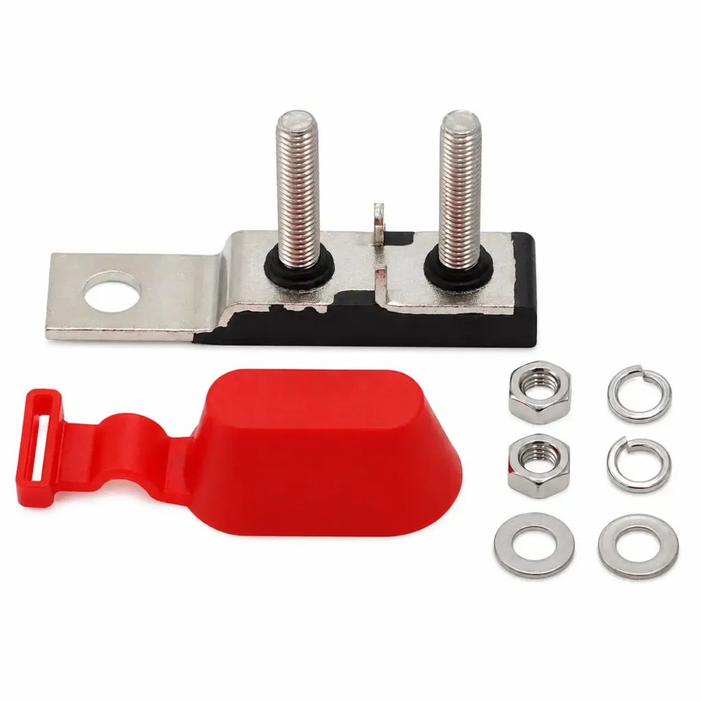
Cozy Electronics currently offers both single- and dual-circuit MRBF fuse holder configurations for high-current DC applications.
Single MRBF Fuse Holder – CZY-FH04
The CZY-FH04 Single MRBF Fuse Holder provides one MRBF fuse position.
According to the current Cozy product drawing, the configuration includes:
- 58V DC application
- Maximum application current: 300A
- M8 stud
- PBS body
- Nickel-plated copper current-carrying plate
- Stainless-steel stud and nut
- Protective cover
Internal link:
Single MRBF Fuse Holder – CZY-FH04https://cozyfuses.com/index.php/product/single-mrbf-fuse-holder/
Dual MRBF Fuse Holder – CZY-FH05
https://cozyfuses.com/index.php/product/dual-mrbf-fuse-holder/
The CZY-FH05 Dual MRBF Fuse Holder provides two MRBF fuse positions for two protected branches.
According to the current Cozy product drawing, the configuration includes:
- 58V DC application
- Maximum total application current: 300A
- Two fuse positions
- M8 studs
- PBS body
- Nickel-plated copper current-carrying components
- Stainless-steel hardware
- Protective cover
The 300A figure is treated as the maximum total application current of the dual holder. It should not be presented as 300A per circuit or 600A total.
View our Single MRBF Fuse Holder for one-circuit battery protection applications.
Dual MRBF Fuse Holder – CZY-FH05https://cozyfuses.com/index.php/product/dual-mrbf-fuse-holder/
For OEM or customized electrical assemblies, provide the system voltage, normal operating current, peak current, required fuse ratings, cable size, installation space and environmental conditions so the appropriate configuration can be checked against the actual application.
Frequently Asked Questions
Is an MRBF Fuse Holder the Same as an MRBF Fuse?
No.
The MRBF fuse is the replaceable overcurrent protection device.
The MRBF fuse holder provides the mechanical mounting and electrical connection for that fuse.
What Does MRBF Stand For?
MRBF stands for Marine Rated Battery Fuse.
The format is widely used beyond marine applications, including automotive, RV, auxiliary battery and other high-current DC systems.
Can a Dual MRBF Fuse Holder Use Two 300A Circuits?
Do not assume so.
A dual holder may have a maximum current limit for the entire assembly. The branch fuse ratings and total holder limit should be checked independently.
Are All MRBF Fuse Holders Waterproof?
No.
A protective cover and a tested ingress-protection rating are not the same thing.
Verify the actual environmental specification of the holder being used.
What Can Cause an MRBF Fuse Holder to Get Hot?
Possible causes include:
- Excessive current
- Loose fasteners
- Poor cable-lug contact
- Contamination
- Corrosion
- Undersized conductors
- Incompatible hardware
- Excessive contact resistance
Abnormal heating should be investigated.
Should the Fuse Holder Be Installed Close to the Battery?
Terminal-style MRBF systems are commonly chosen because they allow protection to be positioned close to a high-current source.
The exact installation location should still follow the electrical design, equipment instructions and any applicable standards.
Is a 300A Fuse Correct Just Because the Holder Supports 300A?
No.
The fuse should be selected from the actual load, conductor protection requirements and equipment specifications.
The maximum capability of the holder is not a fuse-selection target.
Final Takeaway
An MRBF fuse holder provides a compact way to install high-current DC circuit protection close to a battery or power distribution point.
Correct selection involves much more than checking whether an MRBF fuse physically fits.
Consider:
- System voltage
- Normal and peak current
- Cable ampacity
- Fuse rating
- Interrupt rating
- Holder current capability
- Terminal hardware
- Environmental conditions
- Installation quality
For one protected branch, a single MRBF fuse holder may be sufficient.
For two separately protected branches from the same source, a dual MRBF fuse holder can simplify the installation, but its total current limit still needs to be verified.
The most reliable selection process is to start with the load and conductor requirements, then choose the fuse and fuse holder that match the electrical design.