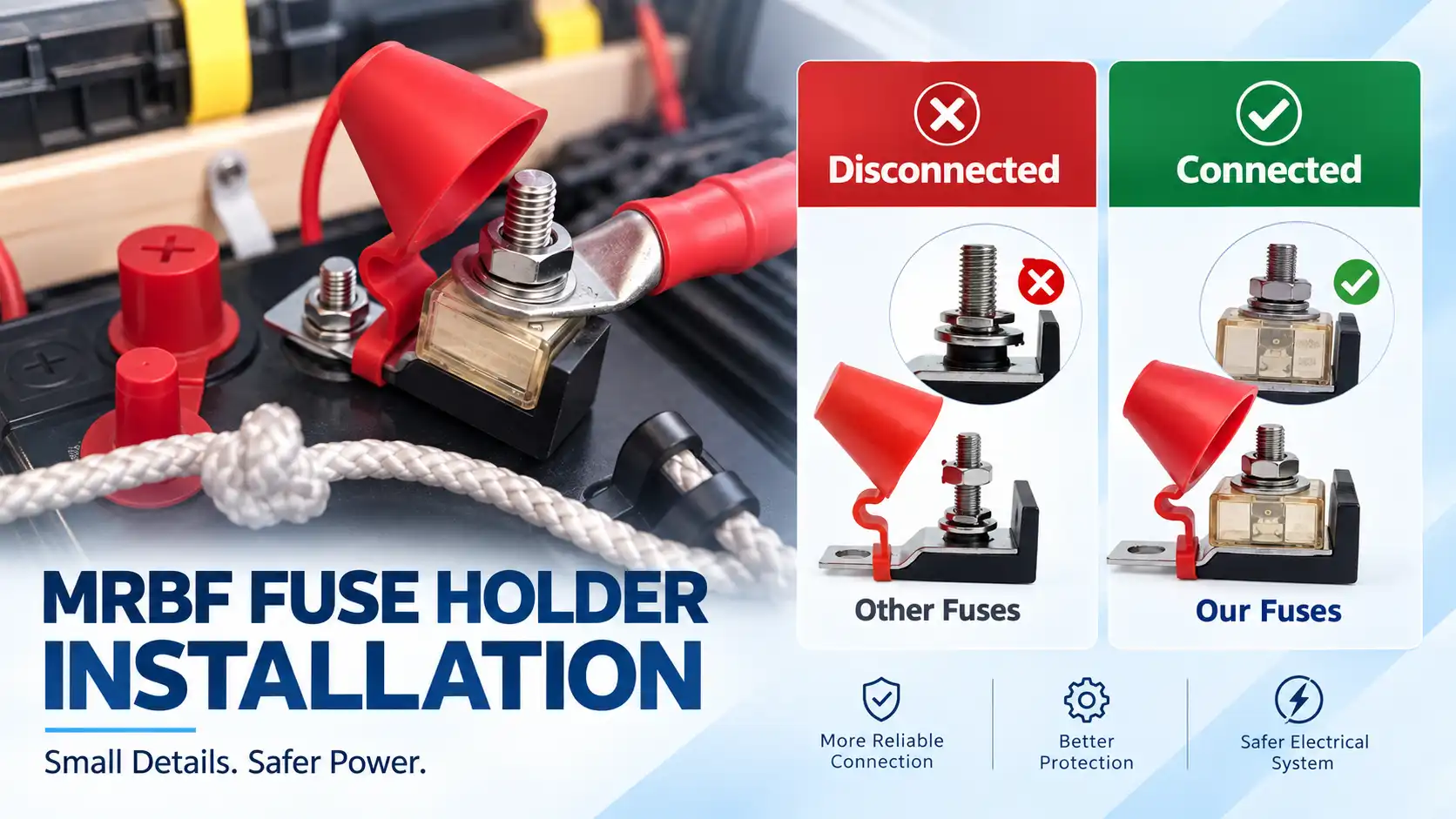
Correct MRBF fuse holder installation involves more than mounting the holder and tightening a nut.
A high-current battery protection connection depends on several parts working together: the fuse, holder, cable, terminal lug, mounting hardware, contact surfaces and the electrical system itself. An unsuitable fuse, poor cable termination, contaminated contact surface or incorrect mechanical connection can reduce the reliability of the complete installation.
This checklist focuses on the practical points to verify before, during and after installing an MRBF fuse holder.
Quick Answer
Before installing an MRBF fuse holder, check these 10 items:
- Is the circuit completely de-energized?
- Is the holder suitable for the system voltage and current?
- Is the MRBF fuse correctly selected for the protected circuit?
- Is the cable size appropriate?
- Are the cable lugs compatible with the holder studs?
- Are all electrical contact surfaces clean and properly seated?
- Is the holder mounted securely with adequate clearance?
- Are bolted electrical connections tightened according to the correct product specification?
- Is the protective cover installed correctly?
- Has the complete circuit been inspected after installation?
For fuse sizing and electrical selection, see our MRBF Fuse Selection Guide before beginning installation.
1. De-Energize the Circuit Before Installation
The first step in any MRBF fuse holder installation is to make sure the circuit is not energized.
Do not install, remove or reposition a high-current fuse holder while the circuit is live.
The exact isolation procedure depends on the vehicle, battery bank, marine system or equipment design, but the goal is the same: prevent unintended current flow while working on exposed conductive parts.
Before starting:
- switch off connected equipment;
- isolate the appropriate power source;
- verify that the circuit is in a safe state;
- prevent accidental reconnection during installation.
High-current battery circuits require particular care because a short circuit can involve much more current than the normal operating load.
2. Confirm the Holder Matches the Electrical System
Before mounting the holder, verify its electrical limits.
Check:
- system voltage;
- expected circuit current;
- fuse format;
- number of required protected circuits;
- total holder current limit where applicable.
Do not assume that two holders with similar physical dimensions have the same electrical capability.
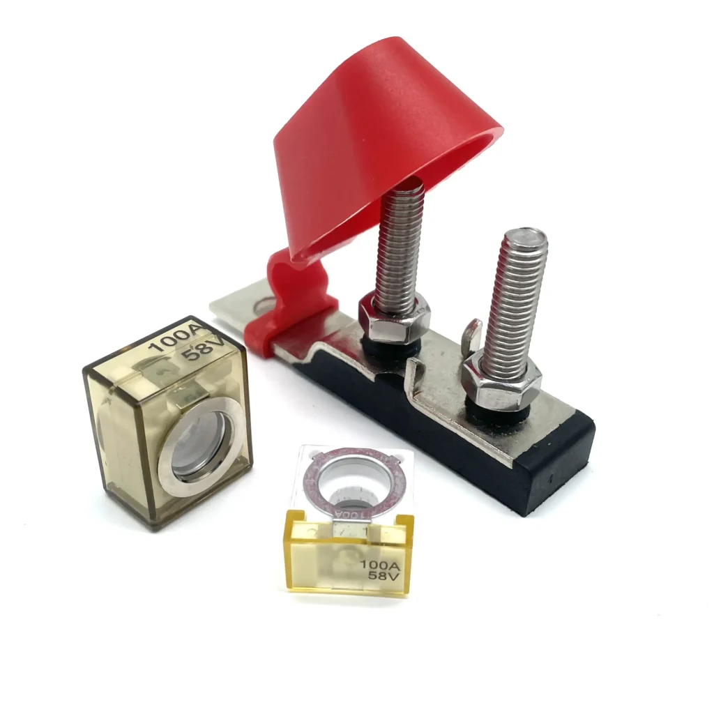
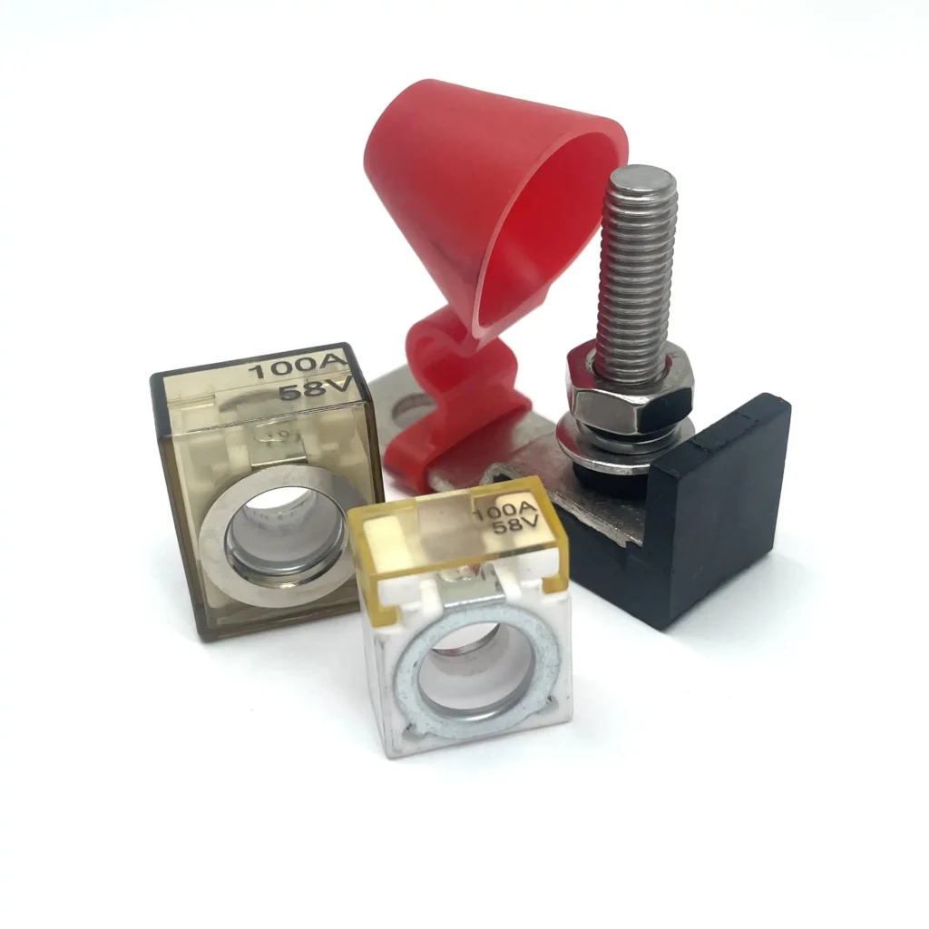
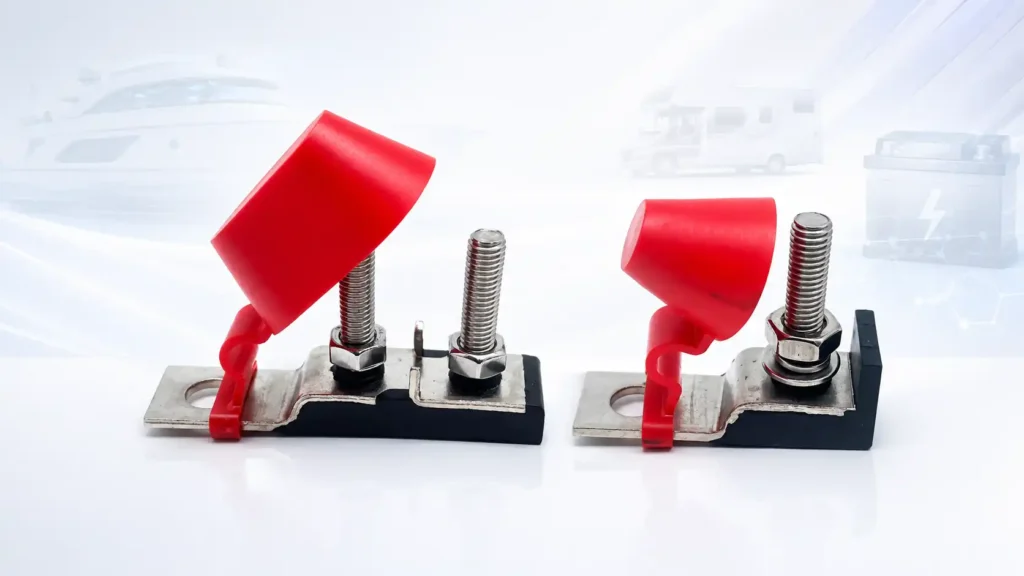
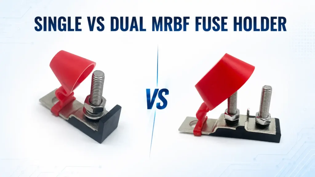
For example, the Cozy CZY-FH04 Single MRBF Fuse Holder is designed for one MRBF fuse position, while the CZY-FH05 Dual MRBF Fuse Holder provides two separately fused positions.
The dual design does not automatically mean twice the total current capability.
For CZY-FH05, the confirmed maximum total application current is 300A.
If you are still deciding between the two configurations, see our Single vs Dual MRBF Fuse Holder comparison.
3. Verify the Fuse Before Installing It
The fuse and holder perform different functions.
The holder provides the mechanical and electrical interface, while the fuse provides the overcurrent-protection function.
The fuse should therefore be selected according to the protected circuit rather than simply according to the largest fuse rating that physically fits the holder.
Check:
- fuse voltage rating;
- fuse current rating;
- conductor protection requirements;
- load characteristics;
- applicable breaking capacity;
- physical compatibility with the holder.
For technical context, ISO 8820-6:2019 defines requirements for a particular class of road-vehicle single-bolt fuse-links rated at 58 V, ≤300 A and 2,000 A breaking capacity. This should not be interpreted as proof that every MRBF fuse or MRBF holder complies with ISO 8820-6.
4. Check the Cable and Terminal Lug
The conductor, terminal lug and holder need to work as one connection system.
Before assembly, confirm:
- the conductor is appropriate for the circuit;
- the lug is correctly sized for the conductor;
- the lug hole matches the holder stud;
- the crimp or termination is properly made;
- the cable is not placing unnecessary mechanical force on the holder.
Both Cozy MRBF holder models discussed in this guide use M8 stud connections, so the terminal lug must be mechanically compatible with the stud.
Do not enlarge a lug hole, force an incompatible terminal onto the stud or rely on loose-fitting hardware to make the connection.
5. Inspect the Electrical Contact Surfaces
The interface between the fuse, conductive plate, lug and hardware is part of the electrical path.
Before assembly, inspect the contact surfaces for:
- dirt;
- oil;
- foreign material;
- obvious oxidation or corrosion;
- physical damage;
- misalignment.
The objective is to achieve stable metal-to-metal contact across the intended conductive interface.
This matters because the resistance of a high-current connection can contribute to local heating.
A 2026 experimental study of bolted power-battery electrical connections found that electrical contact resistance was influenced by bolt pre-tightening, contact area, surface condition and vibration. The study also linked optimization of contact resistance with improved temperature behavior during battery charge-discharge testing.
6. Choose the Installation Location Carefully
An MRBF holder should be installed where the protected circuit, cable layout and service access can be managed properly.
Consider:
- distance from the power source;
- cable routing;
- mechanical protection;
- access for fuse replacement;
- clearance for terminal hardware;
- protective-cover movement;
- exposure to moisture, contamination or physical damage.
One reason terminal-style fuse protection is commonly placed near a battery is to minimize the length of conductor that remains upstream of the overcurrent-protection device.
A regulatory example is found in U.S. recreational-boat rules. Under 33 CFR §183.455, covered ungrounded conductors must generally have a fuse or circuit breaker at the source of power. Where that is physically impractical, the regulation permits specified short distances, including 7 inches or, under additional enclosure conditions, up to 40 inches. The rule also lists exceptions, so these dimensions should not be treated as a universal installation rule for every application.
7. Mount the Holder Securely
The holder should remain mechanically stable after installation.
Before tightening electrical connections, make sure:
- the holder sits correctly in its intended position;
- it does not rock or move unnecessarily;
- cable weight is not being used to support the holder;
- surrounding parts will not interfere with the fuse or cover;
- sufficient room remains for future inspection.
A compact installation is useful, but insufficient service clearance can make future fuse replacement or terminal inspection difficult.
For a dual holder, also consider how two outgoing cables will be routed without placing excessive strain on the shared assembly.
8. Tighten Bolted Connections According to the Correct Specification
Bolted electrical connections should be secure, but more torque is not automatically better.
Insufficient tightening can reduce contact stability.
Excessive tightening can damage threads, hardware, the fuse, conductive components or surrounding insulating material.
There is no single universal torque value that should be applied to every MRBF fuse holder.
Use the documented specification for the exact holder, fuse and hardware combination being installed.
This is especially important because the same-looking M8 hardware does not automatically imply the same tightening requirement across different designs.
The role of preload is supported by experimental work on battery bolted electrical connections, where pre-tightening torque was shown to affect electrical contact resistance.
Important Cozy Product Note
Do not transfer one Cozy model’s drawing value to another model unless the relevant drawing specifies it.
The CZY-FH04 and CZY-FH05 use different product constructions and should be installed according to the specification for the exact model.
9. Install the Protective Cover Correctly
Once the electrical connections are complete, confirm that the protective cover closes and seats correctly.
The cover helps protect exposed conductive hardware from accidental contact and environmental exposure.
Check that:
- no cable prevents the cover from closing;
- terminal hardware does not interfere with the cover;
- the cover is not distorted;
- the cover remains securely positioned after installation.
For Cozy MRBF holders with the protective-cap design, the holder is treated as a waterproof design based on the confirmed product configuration.
However, do not assign an IP rating such as IP65, IP67 or IP68 unless that specific rating has been verified by appropriate testing or documentation.
10. Perform a Final Installation Inspection
Before returning the system to service, inspect the complete installation rather than checking only the fuse.
Verify:
| Check | What to Confirm |
|---|---|
| Fuse | Correct type and rating for the circuit |
| Holder | Correct voltage/current configuration |
| Cable | Properly selected and supported |
| Lug | Correct fit on the stud |
| Contact surfaces | Clean and fully seated |
| Hardware | Correctly assembled and tightened |
| Cable routing | No unnecessary mechanical strain |
| Cover | Properly closed |
| Clearance | Adequate around terminals and fuse |
| Circuit | No obvious loose or damaged components |
After the system has been returned to normal operation, any unusual heating, discoloration, odor, looseness or visible damage should be investigated rather than ignored.
Why Fuse-Link Standards and Fuse-Holder Specifications Must Be Kept Separate
This distinction is important when reading technical documentation.
ISO 8820-1:2014 defines terminology and general test requirements for road-vehicle fuse-links. ISO currently lists the standard as confirmed in 2026.
However, the ISO scope explicitly states that this part of ISO 8820 does not apply to fuse holders used in vehicles.
Therefore:
A fuse standard does not automatically establish the electrical, mechanical or environmental rating of the holder.
The fuse and holder must each be checked against their own applicable technical data.
Cozy MRBF Fuse Holder Options
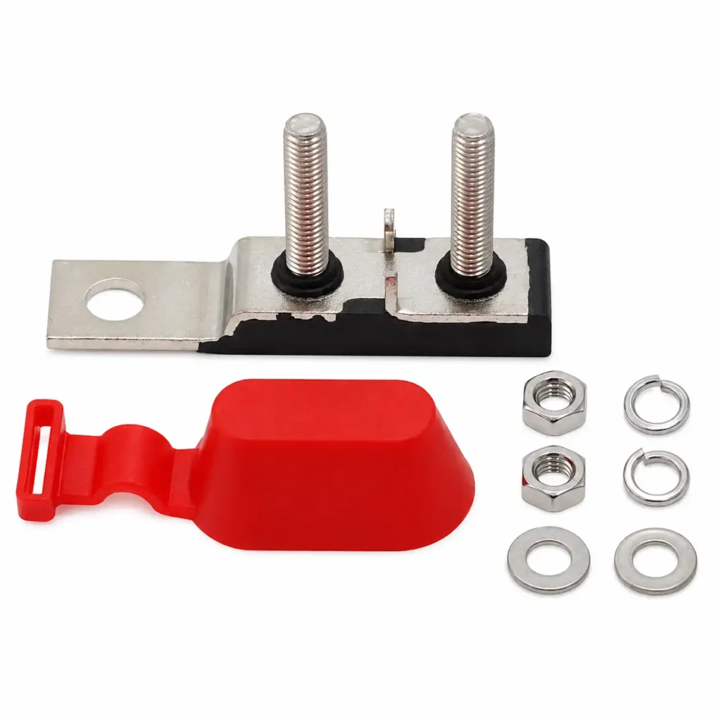
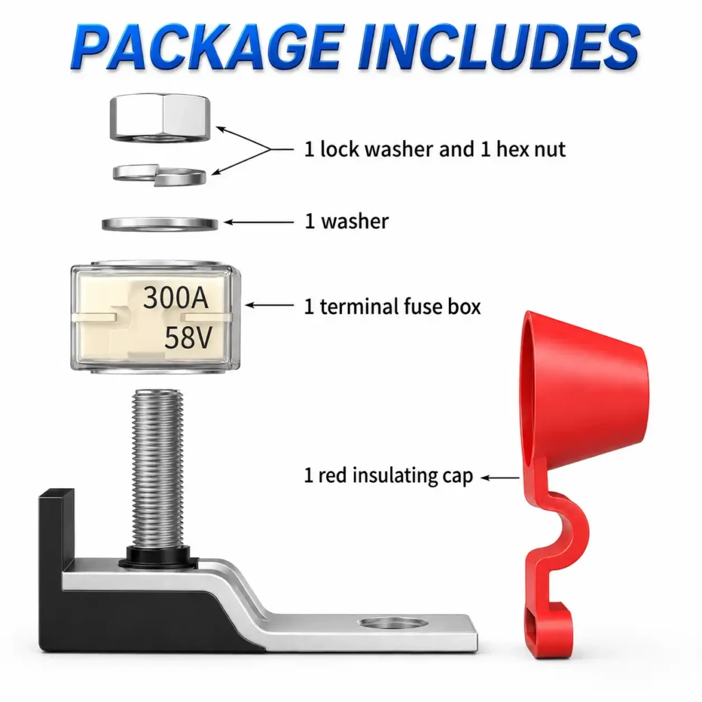
CZY-FH04 Single MRBF Fuse Holder
For applications requiring one protected branch:
- one MRBF fuse position;
- 58V DC application voltage;
- maximum application current 300A;
- M8 stud;
- PBS body;
- nickel-plated copper current-carrying plate;
- stainless-steel stud and nut;
- protective cover;
- waterproof design.
CZY-FH05 Dual MRBF Fuse Holder
For two independently fused branches:
- two MRBF fuse positions;
- 58V DC application voltage;
- maximum total application current 300A;
- M8 studs;
- PBS body;
- nickel-plated copper conductive components;
- stainless-steel hardware;
- protective cover;
- waterproof design.
Frequently Asked Questions
Where should an MRBF fuse holder be installed?
It is commonly installed near the battery or power-distribution source so that the upstream unprotected conductor length can be minimized. Exact placement must follow the requirements applicable to the specific vehicle, boat or equipment.
Can I tighten an MRBF fuse holder as much as possible?
No. Bolted electrical connections should follow the specified assembly or torque requirement. Both insufficient and excessive tightening can create problems.
Why can a loose MRBF connection get hot?
A poor electrical interface can increase contact resistance. In high-current circuits, additional resistance can contribute to localized heating.
Does an M8 stud mean every M8 cable lug is suitable?
The stud-hole size is only one compatibility factor. Cable size, lug dimensions, material, termination quality and installation geometry also need to be appropriate.
Should I install the fuse before connecting the holder?
The circuit should remain de-energized during installation. The exact assembly sequence should follow the holder, fuse and equipment instructions applicable to the system.
Does a waterproof cover mean the holder is IP67?
No. A waterproof design or protective cap should not be converted into a specific IP rating unless that rating has been verified.
Can I use the same installation procedure for single and dual MRBF holders?
The general principles are similar, but the mechanical layout, total current limits and product-specific assembly requirements can differ. Always check the exact model specification.
Final MRBF Fuse Holder Installation Checklist
A reliable MRBF fuse holder installation should confirm five things before power is restored:
electrical compatibility, conductor protection, mechanical compatibility, connection quality and environmental protection.
The fuse should be correct for the protected circuit, the holder should remain within its electrical limits, the cable and lug should fit correctly, bolted connections should follow the applicable specification, and the installation should remain accessible for inspection.
For the complete selection process, continue with our MRBF Fuse Holder Guide and MRBF Fuse Selection Guide.